Advanxis Technologies and Process Automation presents the second edition of The National Automation Competition/Prize on PLC/SCADA Programming/Scripting simulation.
This is Advanxis way of promoting science, Technology, engineering among Nigerians and creating the much needed awareness and knowledge about the Modern industrial production/Manufacturing process.
Advanxis Technologies and Process automation is placing some premium prize and reward to deserving individuals who can prove their mantle in the field of industrial automation. We are rewarding the best PLC programmer and HMI/SCADA graphics developer with the following prize money.
Ist Prize N2,500,000
2nd Prize: N1,000,000
3rd Prize: N500,000
& Lots of consolation Prizes to be won
The task for this year’s Competition/prize is:
Develop Process Control PID re-useable code block and SCADA/HMI graphics faceplate for it
Full Narrative for The Task
A PID controller is the most widely used feedback control algorithm in industrial automation—oil & gas, power plants, water treatment, Flight control System, Drones, compressor control, utilities, etc. Its usefulness comes from its ability to continuously calculate an error ‘e’ Signal and adjust the control output ‘CV’ to keep the process stable, safe, and optimized.
The PID algorithm that governs the output ‘CV’ is expressed as:
CV(t)=Kpe(t)+Ki∫e(t)dt+Kd (dt/de(t))
Where:
- CV(t) = controller output
- e(t)=SP−PVe(t) = error
- Kp = proportional gain
- Ki=integral gain
- Kd=derivative gain
- SP=Set Point
- PV=Process Variable
Let consider a process control for instance a tank, we wish to regulate the level of liquid in it despite the inflow disturbance.
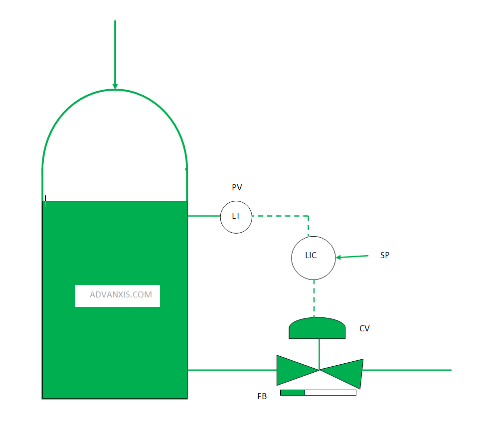
With PID controller expression above we are required to write a Process Control PID re-useable code block in PLC and develop a SCADA/HMI graphics faceplate for such process control as the above figure.
Here is the SCADA/HMI Narrative:
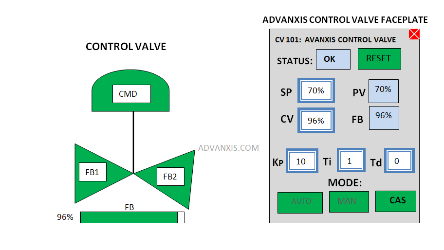
- Status: This is a two state signal which shows that the command on the valve corresponds to the feedback. It is ok if the command corresponds to the feedback or not more than ‘x%’ (typically 3%) deviation from the feedback within a time not exceeding travel time of ‘ys’ (Typically 5s) of the valve, otherwise there is discrepancy/Discordant alarm.
- Reset: This is the reset button to the discrepancy/Discordant alarm of the valve. This alarm is normally latched.
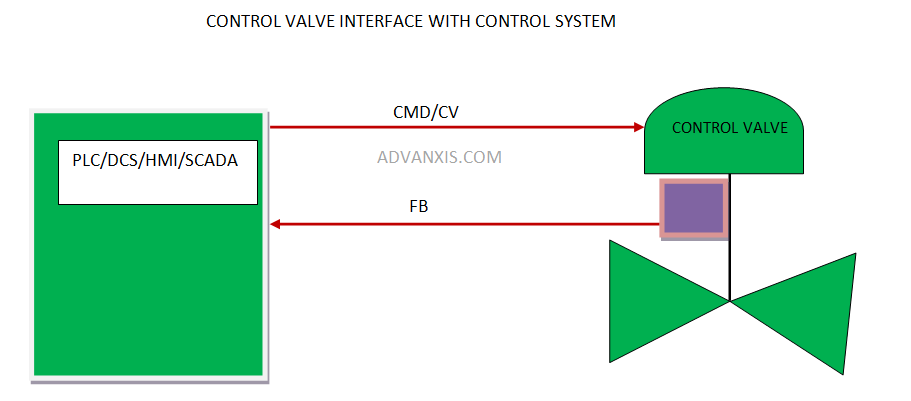
- CMD/CV: This is the analog command signal Output from the PLC/DCS to the valve.
- FB signal: This corresponds to the actual analog feedback signal from the valve.
- Auto/Manual/Cas: Auto means the operator input the set point for the control Valve, CAS meaning cascade which implies that the set point for the control valve is driven by another logic condition while manual means the control valve will be controlled by the operator’s Manual input through the faceplate and involve direct value input to CV.
- Control Valve Animation:
- the CMD top should be green(Open) when the command is greater or Equal to 50% and white(close) when less than 50%
- FB is the analog feedback from the valve positioner and should be animated as a slider proportional to the magnitude of the feedback signal.
- FB1 and FB2 are logical discrete feedback of the control valve and are animated as follows:
FB1 is green when 5%<=FB<=100% and it is white when 0%<=FB<5%
FB2 is green when 95%<=FB<=100% and it is white when 0%<=FB<95%
Entry Procedure
The competition will involve stage 1 or entry stage and stage 2 or the final stage
Stage 1 or Entry Stage
This is the entry stage and it involves non software solution.
Find below the activities for this stage:
- Registration for the competition (Register here)
- once registered you will automatically receive an acknowledgement email
- You will have to proceed to write a summary of not more than three pages on how you are going to approach the solution
- The summary will highlight: the PID Pseudo code for your re-useable function block/subroutine, valve command/feedback subroutine algorithm/pseudo code, the programming language(s) you would employ. Summary of other programming details that would be required to achieve the control narrative and finally the summary of how the graphics animation would be achieved based on the control narrative as well as the process diagram given.
- The entry must be submitted to Prize@advanxis.com
- This stage will end on Saturday 13th December, 2025. Time: 12AM. Hence, all entries must be submitted on or before that time.
- Successful candidate will be qualified for stage 2.
The Second Stage/Final stage
This stage will involve Software implementation of the process logic and graphics. The PLC/HMI/SCADA software of choice are: TIA Portal, Control Studio/Contrologix/FactoryTalk SE/ME as well as Intouch.
Find below the activities for this stage:
- The shortlisted/Successful candidates will be scheduled for 120mins physical/online implementation of the logic/graphics for the process
- The Top successful candidates will be unveiled and the prize money awarded on 20th of December, 2024 which will will also mark our 11th year celebration.
- Venue: Advanxis Technologies and Process Automation Facility, 22 Trans Amadi Road, Trans Amadi Industrial Layout, Port Harcourt.
Hurry up! And register, as registration is still ongoing!
Advanxis @ 11! keep Advanxing!!